| Author | Message | |||
Robert Weisbein (rweisbein) New member Username: rweisbein Post Number: 1 Registered: 05-2005 |
Hello, I'm a new FlexPDE user and am trying to model fluid flow with mass transfer in a pipe. I am using the fluid flow equations that some of the examples use, and a mass transfer with convection equation that's in literature. However, the concentration profile seems almost entirely controlled by diffusion and only influenced by flow very slightly. My model consists of a pipe with flow going from left to right. In the middle of the pipe is a port that injects fluid with a concentration of substance. The flow plots look great, but the concentration plot doesn't look quite right to me. I would expect the concentration to follow the flow vectors more closely and only diffuse away from the path slightly. (Especially when I lower the diffusion coefficient significantly). One other thing: It seems that the concentration reached within the pipe gets much higher than what's being injected. Any Ideas? I will appreciate any and all help. Thanks in advance, Rob
| |||
Robert G. Nelson (rgnelson) Moderator Username: rgnelson Post Number: 365 Registered: 06-2003 |
Your inflow and outflow boundary conditions on C are not correct. 1) On the inlet side (your boundary 8), presumably C=0, so use the boundary condition VALUE(C)=0 2) on the outflow side (your boundary 6), you need a condition that merely carries C out through the boundary. According to the definition of the Natural Boundary Condition (q.v.), the Natural defines the value of the outward normal component of D*grad(C). Since you don't want to put any constraints on this value, but allow it to adapt to internal conditions, simply use the "Tautological" value: Natural(C) = normal(D*grad(C)). The attached graphics show the effect of doing this. Note that since the downwind side of the obstruction is totally blocked from the fluid, you get a high concentration, which is blown away at larger Y by the fluid flow. 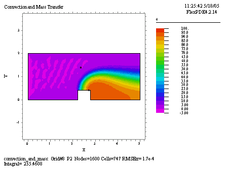 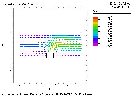 | |||
Robert G. Nelson (rgnelson) Moderator Username: rgnelson Post Number: 366 Registered: 06-2003 |
PS. You could put surface integrals across the injection surface and the outflow surface to check mass conservation. Or just put elevation plots of normal(D*grad(C)) on those planes. | |||
Robert G. Nelson (rgnelson) Moderator Username: rgnelson Post Number: 367 Registered: 06-2003 |
PPS. You have specified for your injection a fixed flux of C (ie, D*grad(C)=1) independent of the fluid velocity. This would seem to be a rather un-physical prescription. I suspect what you want is for the concentration in the injected fluid to be some constant value, like 1, so that the flux is determined by the injected flow velocity. |