| Author | Message | |||
Xi-Feng (country_road) Member Username: country_road Post Number: 13 Registered: 03-2008 |
Dear Robert, First, thank you very much for the help got from you in the past. With some basic understanding, I restart the strain analysis in the spring system. Experimentally, we rotate one end of the spring(with attached wire sample on the surface) with respect of the other end to apply strain. The rotation is done by connecting the top end to a shaft (with pins) with the bottom end fixed. When the shaft is rotated, the top end of the spring rotates. With about -1% uniaxial compressive strain on the outer surface (~ +1.5 uniaxial tensive strain on the inner surface), the angular displacement between the ends of the (4 turns) spring is about 60 degree. I can not make it work. I post the only script which can get the angular displacement( simple one turn spring). But I do not think it is right. I do not know how to put the real BC. Even I am not certain the equations are right or not. I hope I get further help from you or other experts. Thanks
 | |||
Xi-Feng (country_road) Member Username: country_road Post Number: 14 Registered: 03-2008 |
I would like to add some details. Basically,the (+-)sign uniaxial strain on the outher surface always be the opposite to that on the inner surface(- + sign) at any rotation. If the the angular displacement between the ends of the spring is somde angle (e.g. +20 degree), the outer surface is in tensive strain and the inner surface is in compressive strain.If the angular displacement is -20 degree,the outer surface is in compressive strain and the inner surface is in tensive strain. The value of the strain can be measured (calibrated) by the strain gauges. It is simple and stright forward from experiment view. However, how to use PDE to simulate this, I need some help. Thanks | |||
Robert G. Nelson (rgnelson) Moderator Username: rgnelson Post Number: 1195 Registered: 06-2003 |
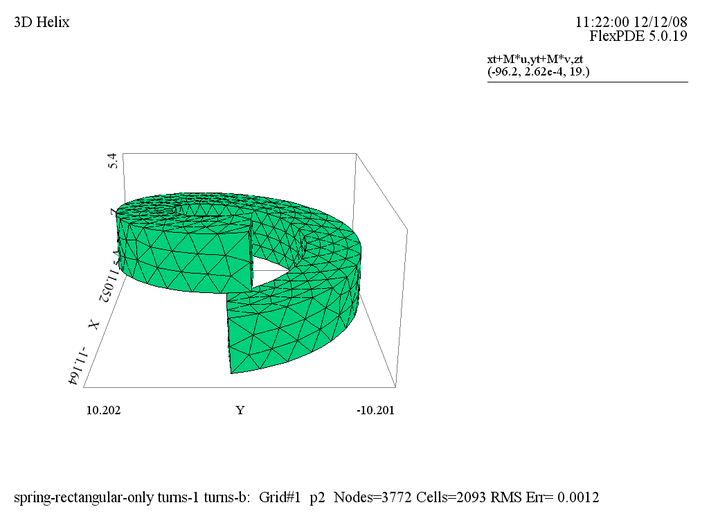
1. I don't understand why you added the body force +K*v to the V equation. This would not seem to correspond to anything in your experimental setup. You should remove it, as I have to create the attached graphic. 2. The displacement equations are written in the "lab" coordinates of the wrapped spring, so the applied forces correspond to this geometry. A force tangential to the coil must be partitioned between the U and V equations according to the angle "alpha", e.g., load(V)=K*sin(alpha); load(U)=-K*cos(alpha). In your case, this amounts to placing the load fully on V, since alpha is pi. 3. Applying a uniform tangential load to the entire end face is not equivalent to applying a torque to the spring. If you simply push or pull tangentially on the spring ends, you will get a sideways offsetting of the spring turns. (See attached graphic). I assume that this is what you saw that convinced you that four turns does not work, but as you see, it works correctly. As you point out, the outside of the spring is tensive and the inside is compressive (or the reverse). This must be reflected in the application of the load to the end of the spring. There must be a radial dependence of the load so that the inner and outer faces feel opposite loads and the position Rn has zero load. You should be able to define a simple radial function, like perhaps (r-Rn)/Rn, and apply this to the K load on the spring end face. 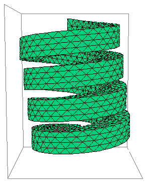 | |||
Xi-Feng (country_road) Member Username: country_road Post Number: 15 Registered: 03-2008 |
Hi, Robert Thank you so much. Your are absolutely right. The force (strain) is proportional to (1-Rn/r). I removed the +K*v term as you suggested. I got lost between the "lab" coordinates and the "XYZ" coordinates, so I can not easily figure out the boundary conditions. One remaining question for me is that I am not clear where the load (force) should be applied. Only on one end with one end clamped? Or on inner surface and outer surcace as well? I can not get the reasonal simulation values at the moment. I think,the boundar conditions are still not right . Experimentally, (unaxial) strain along the whole outer surface (and/or inner surface) is nearly uniform (variation < a few percentage) at specified angular displacement(rotation angle). The results I got are very bad. I will keep trying to work it out. Thanks again | |||
Xi-Feng (country_road) Member Username: country_road Post Number: 16 Registered: 03-2008 |
Hi I have had a simple question for quite long time. Can this problem be solved in the cylindrical coordinates? Because the spring is more close to the cylindrical coordinates than to the Cartesian coordinates. Thanks | |||
Robert G. Nelson (rgnelson) Moderator Username: rgnelson Post Number: 1202 Registered: 06-2003 |
As I said before, you must apply a load on the ends that is representative of a torque, not a sideways drag. This means you must apply a force couple to the end of the spring, corresponding to the proportionality (1-Rn/r). Whether you apply it to one end or both would seem to be a matter of choice. The figure I posted before shows the sideways drag of the spring, which is consistent with the elevation plot of v vs y (attached). The spring bends sharply at the side opposite the sideways drag force, and accumulates a net v displacement. I do not believe you can do this problem in 2D axisymmetric geometry, as a cut plane along the axis would leave the intersected pieces of the spring hanging in space and uncoupled. I do not know how to propagate the strain between the uncoupled pieces. If the coordinate transformation confuses you, perhaps you could try the direct cartesian formulation "Misc/3d_domains/3d_Layered_Helix.pde" included in recent distributions. I attach it here in case you don't have the latest download.
 | |||
Xi-Feng (country_road) Member Username: country_road Post Number: 17 Registered: 03-2008 |
Thanks. I will try what you said. | |||
Xi-Feng (country_road) Member Username: country_road Post Number: 18 Registered: 03-2008 |
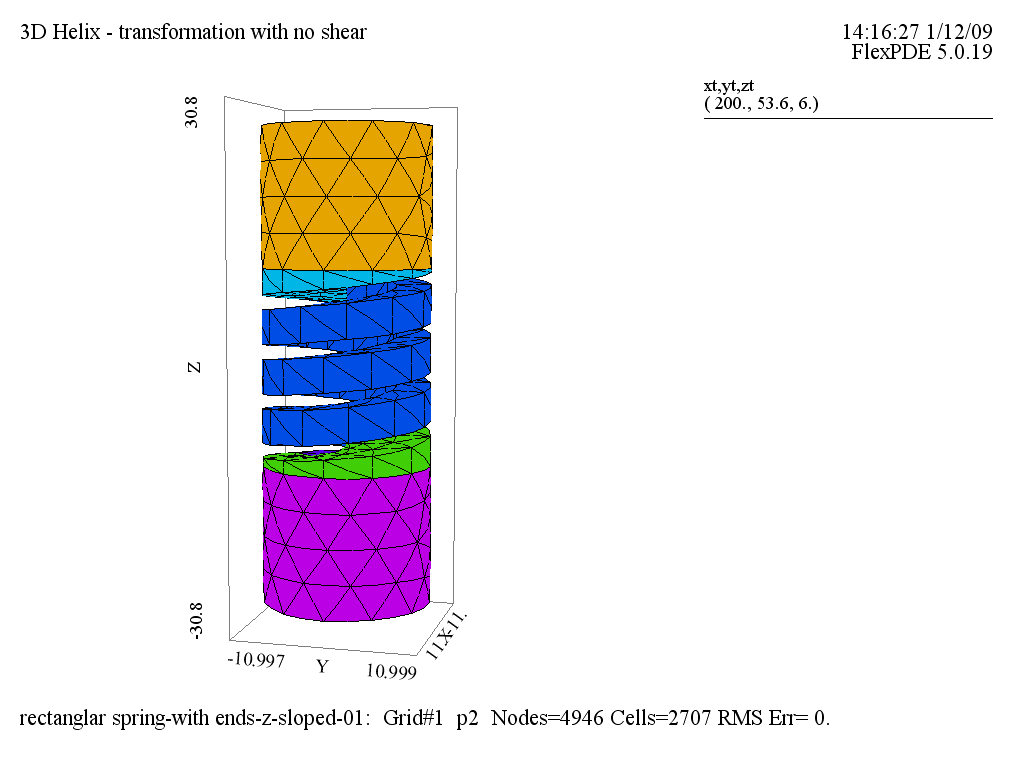
Dear Robert, I have tried the three methods you provided. The PDE software works perfectly to construct the geometry that I need. I get very close to the real thing. However, there is one thing we can not figure it out for all these methods. We want the top (and bottom) blocks (see the attached figure) only can be rotated (except for the z(zt) axis transform) around the z(zt) axis. In other words, I need the top and bottom ends only have rigid rotation movement (with z(zt) axis free). Let�s say 30 degree relative rotation between the top and the bottom blocks. How to write the BC in the attached script? Thank you so much and look forward to your help. | |||
mark creat (markcreat) New member Username: markcreat Post Number: 1 Registered: 01-2009 |
Dear Sir, I focus on the same simulation. And how to apply the rigid angle displacement on the block to make the pure rotation of the spring? Thanks a lot. | |||
David Nandi (danandi) New member Username: danandi Post Number: 2 Registered: 09-2009 |
Hi, I am following on from Xi-feng's work. Could you advise me how to fit end blocks to the cartesian formulation suggested in the 6th post. Thank you | |||
David Nandi (danandi) Junior Member Username: danandi Post Number: 3 Registered: 09-2009 |
This is what I have so far, however I would like the area bellow and above the bottom and top curls respectively to extend to the end rods all the way down.  | |||
Marek Nelson (mgnelson) Moderator Username: mgnelson Post Number: 142 Registered: 07-2007 |
It appears that you have succeeded in adding end blocks to the spring. If what you mean is that you want the spring to extend all the way down, then you need to replicate the layering pattern used for constructing the helical turns. |