| Author | Message | ||||
joe ramas (joeramas) New member Username: joeramas Post Number: 1 Registered: 10-2008 |
I'm trying to design a magnet array that has a field requirement very far away compared to the dimensions of the array (as an example, the muMetal shielding is on the order of 1mm, where as the requirement is 30nT 1M away). I'm having a number of different issues that all revolve around mesh issues. Any help would be greatly appreciated.
| ||||
Marek Nelson (mgnelson) Moderator Username: mgnelson Post Number: 74 Registered: 07-2007 |
If you remove the line "GROW3=10" from your SELECT section, this script grids and runs in about 10 min. The default value for GROW3 is 0.25 and gridding can be very sensitive to this value. GROW3 controls the rate at which cell sizes can grow when moving away from boundary features and if it grows too fast, gridding errors can occur. | ||||
joe ramas (joeramas) New member Username: joeramas Post Number: 2 Registered: 10-2008 |
Thanks Marek. I've just been kinda randomly playing with the mesh configuration since i don't really understand how they will effect my ability to run the script. I've doing a lot of iterations on this design and have been finding it a bit of a rain dance to get them to complete without some sort of "too many neighbors" or other mesh issue. are there some tips and tricks, or perhaps a book that will help me get some intuition on how to tweak my script if it is to error? I have managed to get things to run by arbitrarily changing grow, ngrid, and aspect as well as randomly putting in physically uninteresting regions (and i'm starting now to experiment with layers and limited regions that have the same values as their surrounding region), but the process that i'm using seems incredibly ineffective, inefficient and time consuming. Often the script will run for 1-2 hours before some error or another appears, at which point I randomly change something else. thanks for any further help you can give, joe | ||||
Robert G. Nelson (rgnelson) Moderator Username: rgnelson Post Number: 1186 Registered: 06-2003 |
Can you send us a script that fails? Your original post seemed to work fine once the GROW3 control was removed, so it's hard for us to guess what the trouble is. | ||||
joe ramas (joeramas) Junior Member Username: joeramas Post Number: 3 Registered: 10-2008 |
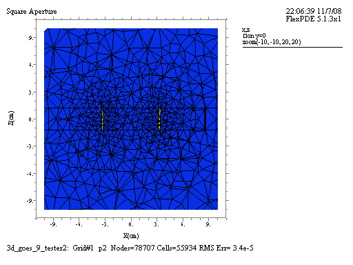
Here's one that i can't get to run at the moment....
| ||||
Marek Nelson (mgnelson) Moderator Username: mgnelson Post Number: 76 Registered: 07-2007 |
Are all the regions with "mesh confiner" in the name your additions to try and control the gridder? If so, please post a script with just the regions of interest for your device. I can't be sure wich regions are important. Thanks | ||||
Marek Nelson (mgnelson) Moderator Username: mgnelson Post Number: 77 Registered: 07-2007 |
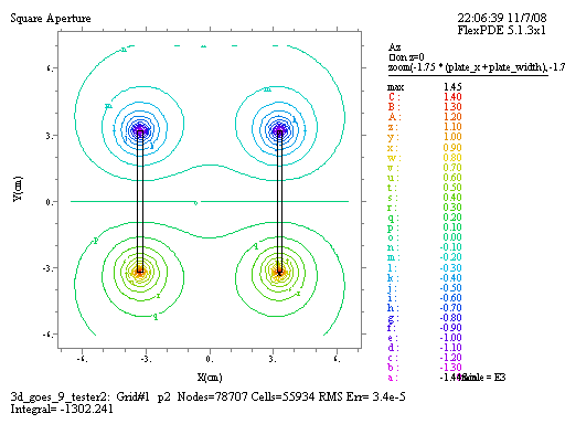
If you just wanted the magnets, here is a script that grids and runs in 4 min. I removed all the extra layers and "confiners" and let FlexPDE grid with the default values for GROW3 and ASPECT.
  | ||||
joe ramas (joeramas) Member Username: joeramas Post Number: 4 Registered: 10-2008 |
Thanks Marek, I'm sorry that the script was so messy, I had thought I should clean it up before sending it off, but I thought it might be good for you to see what i've been trying to do to get it to run with the hopes that you could tell of a more effective way of controlling the mesh. There are two other features that are very important to me in this particular model: "another muMetal shield" as well as a magnet plate that is not currently present in the model that i sent you (with the hopes of trying to get it to run). both of those materials are very thin (on the order of 2mm). The magnet plate that is not present in anyway is a muMetal box that has a 6.4cm X 6.4cm aperture centered about the z-axis on both ends. It encapsulates both magnets, which are mounted directly to it on the inside of the box. geometry: square box of rough inside dimensions x = 7cm y = 7cm z = 5 cm wall thickness of ~2mm with aperture of dimensions x = 6.4cm (full width) y = 6.4cm (full width) such that there is a bore site all the way through the box along the z-axis The outer 'another muMetal shield' is present to shield the magnetic fields. On the design that i sent it is simply a cylinder. It will likely have 'caps' on either end with the same 6.4cm square aperture. geometry: a thin cylinder with center along the z-axis and caps on both ends r = such that it contains the box described above height = such that it contains the box described above wall thickness of ~2mm with aperture of dimensions x = 6.4cm (full width) y = 6.4cm (full width) such that there is a bore site all the way through the box along the z-axis The purpose of this model is to verify that we can achieve <= 30nT @ 1m from the magnet array. Thank you so much for the help that you are offering. I feel that you are going way over and above the call of duty and appreciate it greatly. thanks again, joe | ||||
Marek Nelson (mgnelson) Moderator Username: mgnelson Post Number: 78 Registered: 07-2007 |
I suggest to start by entering only the boundaries of interest (LIMITED when applicable). In general, FlexPDE should be able to grid even small features. When there are difficulties, try using the grid controls MESH_DENSITY and MESH_SPACING instead of adding boundaries. See their entries in the Help index. | ||||
joe ramas (joeramas) Member Username: joeramas Post Number: 5 Registered: 10-2008 |
thanks Marek, I'm starting to play with grid controls now. i think that the issue may be that i'm simply running out of memory. i've noticed that i can always configure the mesh such that it generates more nodes, but seldom can i create mesh's that have less nodes then the default settings. thanks for the tips! Joe | ||||
Marek Nelson (mgnelson) Moderator Username: mgnelson Post Number: 80 Registered: 07-2007 |
By default, FlexPDE controls the mesh size based on the geometry. So, yes, there is a practical limit to the minimum number of cells. 32-bit Windows applications are limited to 2GB of memory. If you are running out of memory, the easiest thing to do is try to reduce the problem size by symmetry. i.e. try cutting your device into fourths on the x=0 and y=0 plane and model just the quarter (your BCs will have to reflect this). You may also be able to model the top half only (symmetry around z=0). | ||||
joe ramas (joeramas) Member Username: joeramas Post Number: 6 Registered: 10-2008 |
Thanks for the advice Marek. This symmetry concept sounds wonderful, unfortunately i don't understand how to do it. I assume that there is some way of setting up (natural(A) = something) on the symmetry plane, but I'm having a hard time understanding what "natural" BC's do or how to set them up correctly. | ||||
Marek Nelson (mgnelson) Moderator Username: mgnelson Post Number: 82 Registered: 07-2007 |
You can use a NATURAL(A)=0 or NOBC(A) on a symmetric plane or Value(A)=0 on antisymmetric plane. Your problem appears to symmetric on x=0 and antisymmetric on y=0 and z=0. I have attached an attempt to do this, but you will have to decide what is correct for your problem. FlexPDE integrates all second order terms by parts. This creates surface integral terms. The NATURAL provides the integrand of the surface integrals. Your Az equation is basically div(grad(Az)/Mu)=0. So the NATURAL provides the value of the outward normal component of the argument of the divergence. ( In your case grad(Az)/Mu ). There are several discussions of this in the Help index under "Natural Boundary Conditions"
|