| Author | Message | |||
Xi-Feng (country_road) New member Username: country_road Post Number: 1 Registered: 03-2008 |
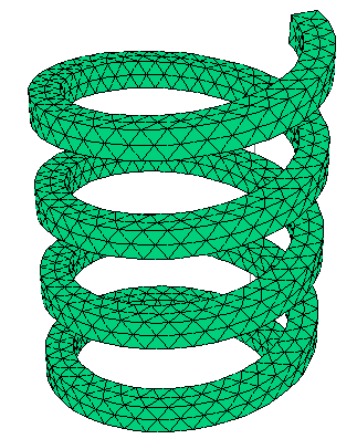
Is there anyone who have good idea about how to construct a helical spirng? (Just specifiy is as follows: The cross section of the turns is rectangular(4.5X4.5 mm), and the OD diameter of the spring is 22 mm(cylinder). The length of the spring is about 60 mm in 4 turns. In our case, we will finally rotate one end with respect the other end to apply compressive and tensile strain.) I am a layman of PDE, and the above case seems too difficult to me. Look forward to your helping. Thans a lot in advance | |||
Robert G. Nelson (rgnelson) Moderator Username: rgnelson Post Number: 1076 Registered: 06-2003 |
One way to do this is to construct a bar and wrap it around a cylinder by coordinate transformation. The method is similar to the example problem "Samples|Misc|3D_Domains|3D_Twist.pde". The attached script describes the method in comments.
 | |||
Xi-Feng (country_road) New member Username: country_road Post Number: 2 Registered: 03-2008 |
Thanks a million. The is exactually what I want. Actually, the real spring we used was 4 turns+rods(at both ends),(see the attached picture). I am wondering how to construct it. Can put more turns and fix the 1st and 4th turns by some constraint or something else? 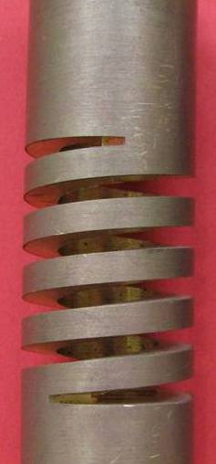 | |||
Robert G. Nelson (rgnelson) Moderator Username: rgnelson Post Number: 1077 Registered: 06-2003 |
The coordinate transformation is applied to the entire domain, so there are limits to what can be done. In your case, it looks like an initial shape with blocks on the ends (a reversed "C" shape) would transform the end blocks into rods. Extend the blocks in Z (two added layers: downward on the bottom and upward on the top). Don't run the blocks all the way to x=0, though, because there are some 1/x terms. This will leave a small hole in the axis, but maybe the effect will be small. There is another way to address this problem: by building the domain up in real space with layers containing half-turns. I will need to do some experiments with this, because we haven't done it before and there are some issues to resolve. | |||
Xi-Feng (country_road) Junior Member Username: country_road Post Number: 3 Registered: 03-2008 |
Thanks a lot. You are so nice and a real expert. I will look you method carefully and think about it hardly. If I can get any further information about this case, I would appreciate. Thanks again. | |||
Robert G. Nelson (rgnelson) Moderator Username: rgnelson Post Number: 1078 Registered: 06-2003 |
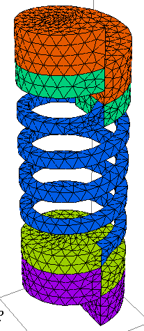
Here is a modification with a heavy piece at each end to simulate the rod. It is not exact, of course, but it should be similar. I added a strain-relief fillet where the spring joins the rod, but I see from your photo that this is wrong. You will have to take it out. Note that the heavy turns at the ends appear in the plots to meet after one turn. This is an illusion, as the computation is really done in the unrolled configuration, where the surfaces do not contact. If you make the z-surfaces slope toward z=0 in the end patches, you can reduce the pitch of the rod end turns.
 | |||
Xi-Feng (country_road) Member Username: country_road Post Number: 4 Registered: 03-2008 |
Thank you so much. This is definitely cose to what I want. There is one thing I need to add is that both ends of the real spring are not rods but cylinders having the same ID and OD as the turns.I should mention that earily and sorry for that. I will learn and practise your example. Thanks again. | |||
Robert G. Nelson (rgnelson) Moderator Username: rgnelson Post Number: 1079 Registered: 06-2003 |
Here is another way to do this. Instead of using a shearing transform in Z, I wrap the core layout directly around the cylinder. This requires ramping the z coordinates in the untransformed layout. In the attached script and graphic, I have made the bore radius smaller than the spring radius, just to accentuate the changes. You can set it back by redefining xbore=xin.
 | |||
Xi-Feng (country_road) Member Username: country_road Post Number: 5 Registered: 03-2008 |
Thank you. I will try this later. Thanks again. | |||
Xi-Feng (country_road) Member Username: country_road Post Number: 6 Registered: 03-2008 |
Do you think it is possbile to choose the cylindrical coordinates? The reason is I do not know how to put a round wire (D=0.8 mm)along the (outside,in the middle ) whole turns? In other words, I do not know how to construct the round things by extrusion in coordinate transformation. Thanks a lot in advance. | |||
Xi-Feng (country_road) Member Username: country_road Post Number: 8 Registered: 03-2008 |
I figured out how to construct the wire separately(as attached script), the prolem left will be how to make the wire and turns generated together. Thanks a lot.
| |||
Robert G. Nelson (rgnelson) Moderator Username: rgnelson Post Number: 1090 Registered: 06-2003 |
I don't understand what you want to do. Please send a picture. | |||
Xi-Feng (country_road) Member Username: country_road Post Number: 9 Registered: 03-2008 |
I got it(as attached picture). But I still had a problem the wire and the spring fully contacted. Thanks a lot. 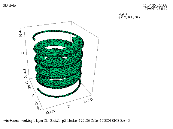 | |||
Xi-Feng (country_road) Member Username: country_road Post Number: 10 Registered: 03-2008 |
Although I got it(as attached picture),I still had a problem to make the coil and the spring fully contacted. (Error: Surface is discontinuous.). I also can not make the coil and spring flushed at both ends when the turns increasing(more than 1 turns). Thanks a lot.  | |||
Marek Nelson (mgnelson) Moderator Username: mgnelson Post Number: 32 Registered: 07-2007 |
You should post a copy of your script file (*.pde) so we can take a look at it. | |||
Xi-Feng (country_road) Member Username: country_road Post Number: 11 Registered: 03-2008 |
Ok, I will post the script file next time. Because the script is quite messy after been changed hundreds of time. I will make it better and post it next time. Thanks a lot. | |||
Robert G. Nelson (rgnelson) Moderator Username: rgnelson Post Number: 1092 Registered: 06-2003 |
You will need to split the rectangular coil on the mid-plane and run the two surfaces that define the circular wire through the midplane of the rectangle. All extrusion surfaces must be continuous throughout the domain, so you can't just jump from the waist of the wire to the top of the rectangle. You will now have three layers with four dividing surfaces. The bottom and top layers are the top and bottom halves of the rectangular spring, and the center layer is the wire. The center layer will be merged in the spring region, and the top and bottom layers will be VOID in the wire region. Also, you will have to move the wire slightly inward to create an area of overlap between the spring and the wire. Otherwise the vertical tangency will cause trouble in the mesh generator. Also, without a small overlap, you would have only a single mathematical point contact, and nothing could be propagated between the wire and spring. | |||
Xi-Feng (country_road) Member Username: country_road Post Number: 12 Registered: 03-2008 |
Thank you very much. It seems now I can understand how PDE works by your explaintion. I will try according to your suggestion. Thanks again. |