| Author | Message | ||||
muneer Ismael (muneer) Member Username: muneer Post Number: 4 Registered: 12-2007 |
Dear Dr. Robert Nelson I am simulating a liquid flow through a pipe. This flow not completely fills the pipe i.e. a flow with a free surface. The liquid free surface is wavy rather than plane. I am interesting in solving only the liquid filled domain. I hardly tried to achieve this domain by the nominal procedure of extruding the flow cross-sectional area (x,y) along the pipe axis (z-axis) but I failed because of the wavy (sine wave) flow along the z-axis. Hence I resort to extrude two curved surfaces (not along pipe axis in this case); I succeeded in simulating the liquid flow domain (as you can see in the following pde text below), but I am facing now another problem this is; how I can fix a boundary condition on a definite portion of the pipe wall. In other words if you run the following pde file, I need to fix the value of u on the two positions these are: 1- value(u) on a circle (with radius say a) and its center at z=0, y=3,x=-1 2- value(u) on a circle (with radius say a) and its center at z=0, y=3,x=1 The file is: title 'Partially-Filled Pipe Flow' coordinates cartesian3 select regrid=off ngrid=20 Variables u definitions w=grad(u) er=0.2 Rt = 1 a=0.08 xc=0.94 f=2 level=0.7 ZL = sqrt(Rt^2-x^2) Zs=level+a*sin(y*pi*f) equations div(grad(u)) = 0 Extrusion Surface "Bottom" z = -ZL Surface "Top" z =min(zL,zs) Boundaries surface 1 natural(u)=0 surface 2 natural(u) = 0 Region 1 start(1, 3) line to(1,3) line to (1,6)to (-1,6)to (-1,3) line to (-1,3) line to(-1,0)to(1,0) to close plots grid(x,y,z) contour(u) on surface x=0 contour(u) on surface y=3.1 elevation(u) from (1,0,0)to (1,6,0) end | ||||
Robert G. Nelson (rgnelson) Moderator Username: rgnelson Post Number: 1032 Registered: 06-2003 |
First, you have a problem where the sine surface intersects the cylinder. FlexPDE needs to know a definition of the boundary between the two surfaces, so that cell boundaries can be forced onto the intersection. This is tricky. You would be better off if you rotate the figure 90 degrees about the tube axis, so that the sine surface is a vertical sidewall. This would also make it easy to define your circles. Simply define a region describing the circle. Since the sides of the tube are now the bottom and top of the figure, a single circle will extrude through bottom and top surfaces. You can define VALUE(U) on these two surfaces in the new region. | ||||
muneer Ismael (muneer) Member Username: muneer Post Number: 5 Registered: 12-2007 |
My Dear Dr. Robert Many many thanks for your replaying. Know I recognizing that the nominal extrusion is more simple, i.e. ploting a surfce (cirular cut from it a portion)in xy plane and then extrosion along z axis (pipe axis). My question now is: Is it possible to make cross section varying along the extrosion, Or in other words (for more clarifying) is it possible to make a cube where the bottom of this cube is flat while the top has a taper (slope) along z axis (of extrosion) Many thanks for your efforts. | ||||
Marek Nelson (mgnelson) Moderator Username: mgnelson Post Number: 12 Registered: 07-2007 |
The extrusion sidewall can only be vertical. As for a cube with a tapered top, this can easily be done and there are numerous examples in "Samples | Misc | 3d_domains". I have created a simple set of scripts showing how to make your sine surface as a vertical sidewall. The first script "export_sine.pde" tabulates and exports the points for the sine function to a file 'sinetable.txt'. The second script "side_sine.pde" creates the pipe with the sine surface sidewall by importing the points from 'sinetable.txt'. This uses line segments for the sine function, but could easily be changed to use a spline instead. See SPLINE in the help index. 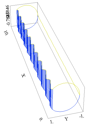
| ||||
muneer Ismael (muneer) Member Username: muneer Post Number: 6 Registered: 12-2007 |
My Dear Tutor Marek Nelson You have no idea how I wish to express my thanks for your efforts.My problem now is how I can impose a boundary conditions on the curved sidewall but for a specified portion say:for x=from 4 to 6 and an angle of 15 degrees on both curved sidewall. Is the FEATURE solve it. | ||||
Marek Nelson (mgnelson) Moderator Username: mgnelson Post Number: 13 Registered: 07-2007 |
If you want to place a boundary condition on just a portion of the top and bottom (the curved sidewall of the pipe), you can define a region that will project to a patch on the top and bottom. i.e. REGION 2 surface 1 BC surface 2 BC start ... | ||||
Marek Nelson (mgnelson) Moderator Username: mgnelson Post Number: 14 Registered: 07-2007 |
I forgot to mention that you will likely want to use a LIMITED REGION. |