| Author | Message | ||||
Massimo Kubon (m_cube) New member Username: m_cube Post Number: 1 Registered: 09-2007 |
Hi everyone, I'm a new user of FlexPDE. Probably 5 days from now... I think I have a very straight forward issue with extrusions. What I'm trying to construct is a 3D Domain with a simple "ramp-up" /"ramp down" principle. One volume shall show a ramp going up defined by a extrusion with a linear function. A second volume shows a straight portion, whereas a third volume shall show a ramp going down defines by the negative linear function. The problem here is: 1) My file programmed shows that my ramp is upside down. 2) I can't connect a second region, because it is discontinuous in some point. Would be glad to recieve any help... M. Cube
| ||||
Robert G. Nelson (rgnelson) Moderator Username: rgnelson Post Number: 956 Registered: 06-2003 |
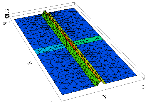
1) Extrusion surfaces must be defined in order of increasing Z (ie, the text lines are upside down from the final figure). 2) Each extrusion surface must be continuous throughout the (X,Y) extent of the problem. 3) the included volume is the volume contained between the defined surfaces. The first surface you have defined (z1) is a ramp rising from z=0 to z=1.48. This is therefore the bottom of your figure, just as shown in the final mesh. If you want to include the volume between z=0 and z1, then your bottom surface must be defined as z=0 and the top surface as z1. if you want to build a trapezoid with base at z=0 and a top surface rising, then flat, then falling, then you must: 1) define a bottom surface at z=0 2) define a top surface (z1) that rises, goes flat, and falls. | ||||
Massimo Kubon (m_cube) New member Username: m_cube Post Number: 2 Registered: 09-2007 |
Hi, I knew it must be as simple as that. Thank you very much. Helped a lot! M. Cube | ||||
M. Cube (m_cube) Junior Member Username: m_cube Post Number: 3 Registered: 09-2007 |
Hi, Now there occurs another issue! ;-) Since I managed to extrude my tapezoid volume, everythings fine until then. Now I'm trying to integrate it into another volume. The "main volume" of my analyzed part. I know that by definition, FlexPDE doesn't count for for limited regions within a region. But is there a possibilty to show my trapezoid? When I switch my trapezoid to a "normal" region, I will have my discontinuous problem again. Is there maybe a way to merge the trapezoid with the volume made in the "bottom layer"? You already showed a possibilty in the quarterhole.pde. http://www.pdesolutions.com/discus/messages/4/1210.html Is there a possibilty to use this approach? And if so, how? Thanks, M. Cube
| ||||
Robert G. Nelson (rgnelson) Moderator Username: rgnelson Post Number: 958 Registered: 06-2003 |
It's not clear to me what you want the final thing to look like. Can you post a sketch? | ||||
M. Cube (m_cube) Member Username: m_cube Post Number: 4 Registered: 09-2007 |
Hi Mr. Nelson, I have to admit the explanation wasn't very significant. I have drawn a sketch of my problem. See the pdf included. I bet it can be solved very easy. I just don't have any clew anymore. I tried a lot of things... thanks for you time Massimo
| ||||
M. Cube (m_cube) Member Username: m_cube Post Number: 5 Registered: 09-2007 |
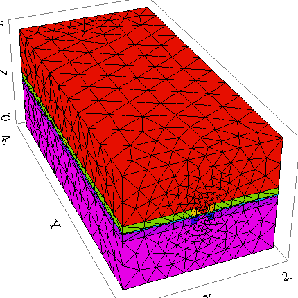
Hi Mr. Nelson, I also added the pde-file from the 3D design I did so far. It shows the 3D Design of an dielectrophoretic (DEP) chip. By remodeling this bar into an trapezoid, I'm trying to optimize the DEP field. Massimo
| ||||
Marek Nelson (mgnelson) Moderator Username: mgnelson Post Number: 1 Registered: 07-2007 |
Your option 2 is the correct way to proceed. You must define a function for your surface "S1" that climbs up and over the trapezoid (and similar for "S4"). This surface definition can be done in one of two ways (both are demonstrated in the attached files). 1 - define a global surface function or 2 - define independent values of the surface in each region (all the separate values must meet to form a continuous surface). I have used the URAMP function to do some of the arithmetic in forming these surfaces. This surface definition causes the surfaces "S1" and "S2" to merge at the top of the trapezoid. So you must create a new region to bound the merged area. This is necessary because you cannot have only a portion of a region merged. (In your case this merged region was part of region 1.) The corner at the bottom of the trapezoid must correspond with a gridding line so that cell boundaries lie on the break. I did this by defining a pair of FEATURES to delineate the outer edges of the trapezoids. This is to ensure that the gridder has a clean edge in the surface. Because "S1" merges with "S2", the boundaries of your embedded region "Region des Spaltes" must be forced into the "S1" boundaries (similarly for "S4"). I did this by including the two adjacent layers ("L1" and "L3") in the "Region des Spaltes". See the attached scripts.
  | ||||
M. Cube (m_cube) Member Username: m_cube Post Number: 6 Registered: 09-2007 |
Thank you very much. It totally helped me a lot. Especially that I got to know the functions. Now everything works perfect! Initially, I also tried to use the FEATURE function from the pyramid example. Unfortunately, it didn't work the way I used it. Thanks also for corresponding to the german description, which I totally forgot to translate. M.Cube |