| Author | Message | ||||
Britta Hagmeyer (britta) Member Username: britta Post Number: 15 Registered: 11-2006 |
Hello everyone! Please take a look at the 3D-FlexPDE-Model I've constructed. I'm simulating particle transport in an incompressible fluid via diffusive transport and via the velocity profile derived from the Navier-Stokes equations. The simulation's initial velocity profile does not equal 0; I've been running a steady-state simulation with the initial velocity and imported the mesh into the time-dependent simulation using the TRANSFER command. The particle velocity caused by the instream of particles through a hole in the bottom of the cylinder is being calculated using the volume flow (calculated by the law of Hagen-Poiseuille) out of this hole into the cylinder. The thus calculated velocity is quite high... is the calculation correct? For testing, I turned off the diffusive transport in the cylinder and expected a concentration profile shaped like the particle's velocity profile, but that was not the case. The particles remain just above the bottom and do not spread out like I would have expected, considering the velocity profile. Thus, the concentration just above the membrane increases with every time step, resulting in weird particle flow into and out of the cylinder through the bottom hole. With this, the amount of particles in the system does not remain constant. Next, I reduced the particle velocity by multiplying the calculated velocity with 1e-4. The particles remain just above the membrane and do not spread, but the amount of particles in the system does not exceed the amount I set available in the system. Turning the diffusive transport back on, the simulation produces results that seem reasonable. But I do not believe reducing the velocity is the key to obtaining a correctly working simulation. What I do not understand is: Why are the particles not moving away from the bottom of the cylinder, considering just the Navier-Stokes velocity profile and not the diffusive transport? Is the velocity calculation correct? Have I implemented the coupled diffusion equation correctly so that it also takes the change due to the particle velocity into account? Should I add another component to the equation that ensures mass conservation? If so, how is this to be done? Do I have to change the simulation parameters? I hope you can help me! Cheers, Britta
| ||||
Robert G. Nelson (rgnelson) Moderator Username: rgnelson Post Number: 955 Registered: 06-2003 |
This problem appears to be azimuthally symmetric. Is there a reason why you are not doing this in 2D cylindrical geometry? It would run a lot faster! | ||||
Britta Hagmeyer (britta) Member Username: britta Post Number: 16 Registered: 11-2006 |
Hello Mr. Nelson! I've changed the 3D system to a 2D cylindrical system. For tryout, I left out the Navier Stokes velocity calculation. All but one result are the same as in the 3D-system. The concentration profile and the amount of particles in the system do not match the 3D data. As I see it, the source of it is the result of the calculation of the capillary pressure pcap, it looks different from the result obtained from the 3D system. Why is that so? I've included my 2D cylindrical system code. Thanks! Cheers, Britta
| ||||
Robert G. Nelson (rgnelson) Moderator Username: rgnelson Post Number: 957 Registered: 06-2003 |
I don't know what you are doing with all the droplet stuff, so I can't comment on that. But in your 3D model, the transport was dominated by the flow velocity, while in the 2D, you have only diffusion. So there is no way the two could get comparable penetrations. You appear to be driving in a mandated flux, regardless of the ability of the material to diffuse it away, so U at the boundary merely rises high enough to store the forced flux. The flux into the material is -D*grad(u). Your BC flux appears to be about 5.5e-4, while D is approximately 5.5e-10. So you need a u-gradient of about 1e6 to carry the concentration away. This is achieved by a buildup of u~1 in a layer about 1e-6 thick. You therefore need a mesh with cells about 1e-6 thick, or the interpolation will not be able to resolve it. By setting ERRLIM=1e-2, you have told FlexPDE not to worry too much about errors, so it doesn't refine the mesh, and you end up with nothing but noise. So... 1) what happened to the flow velocity that was there in the 3D? 2) you need to put in a mesh control of perhaps r_ben/20 in the pore. 3) why is the input flux dissociated from the ability of the host material to carry away the injection? Is this some kind of hydraulic piston that jams the stuff in, no matter what? Incidentally, the TIME statement takes a single end time, and a single initial timestep. It is not a cascade of intervals like a print time selector. | ||||
Britta Hagmeyer (britta) Member Username: britta Post Number: 17 Registered: 11-2006 |
Hello Mr. Nelson, I've created a 2D cylindrical model for my simulations with the velocity profile and removed all mesh restraints. About the TIME statement: If I change the timestep, the concentration profile changes, too, and it is not identical to the concentration profile of the 3D model without the mesh constraints. Does that mean the calculation is getting more precise the smaller timesteps I choose? How can I compare it to the 3D model data? Why do they not coincide? Somehow the simulation with the velocity profile is not working correctly... I want to put a contstraint on the number of particles (INTEGRAL(u)) in the system, meaning there is just a limited amount of particles (a_drop in the model code) available for injection into the system. If this amount has entered the system, the amount of particles should not increase any more. How can I achieve this? Do I have to change something in the calculation of the flow J and J_hp into the cylinder? J and j_hp are fluctuating, and so does INTEGRAL(u). I've coupled the calculation of j and j_hp with the amount of particles in the system (INTEGRAL(u)) and the amount of particles available (a_drop). In the simulation with just diffusive transport, this worked just fine, and the amount of particles in the system was just as I wanted it to be. But with including the velocity profile, that's not the case anymore. Why is that? I've tried various things... if I take the particle flux in the system caused by the velocity (vDOTgrad(u)) out of the calculation of the particle concentration u, the system works fine, and j and j_hp behave normally. As soon as I include vDOTgrad(u) into the system (as in the attached system code), j and j_hp start fluctuating, and the amount of particles in the system gets way too much. What am I missing?? What exactly do you mean by associating the input flux with the ability of the host material to carry away the injection? Injecting more particles into the system only if the particles in the system have diffused away? What would I have to change in my model to achieve that? What would that mean for the 'real-life' model? Thanks for your help! Cheers, Britta
| ||||
Robert G. Nelson (rgnelson) Moderator Username: rgnelson Post Number: 963 Registered: 06-2003 |
The transported flux of U is V*U-D*grad(U). The conservative equation for U is then u: -dt(u) + div(D*grad(u)-v*u) = 0 FlexPDE will apply the divergence theorem to this equation and identify the Natural(U) boundary condition with the inward flux (D*grad(U)-V*U). Your existing equation has v*grad(u) outside the divergence, so it is not integrated by parts and creates no surface terms. Write your equation as I have shown it above, and you will get Integral(u) rising smoothly to 2.0e-14. 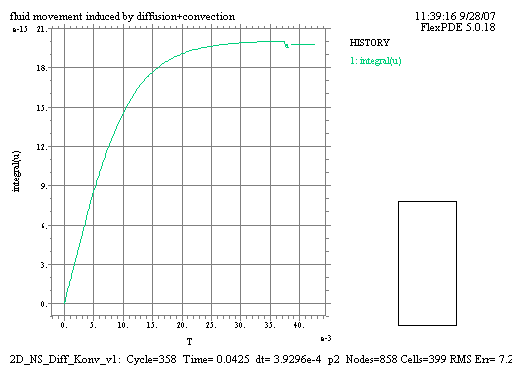 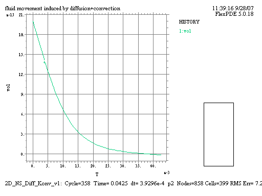 |