| Author | Message | |||
Augusto (cdfx) Member Username: cdfx Post Number: 4 Registered: 04-2007 |
I need a help to build this mesh (exactly) but FlexPDE says : Cell 1 Nabor 131 Nonreciprocal! Mesh is tangled near (-0.06, -0.06)! Continue ? Well, this experiment running fast when I modify the EXTRUSION to remove the tangled surfaces in a centered cube. But now the program can't process correctly. TITLE 'Mod Quinconce 3D' COORDINATES cartesian3 VARIABLES vx, vy, vz SELECT { method controls } ngrid = 1.0 / 70.0 errlim = 0.001 DEFINITIONS { parameter definitions } min_domain = -0.1 max_domain = 1.1 min_cube = 0.2 max_cube = 0.8 K = 1 { default conductivity } ! INITIAL VALUES EQUATIONS vx : div(k*grad(vx)) = 0 vy : div(k*grad(vy)) = 0 vz : div(k*grad(vz)) = 0 ! CONSTRAINTS { Integral constraints } EXTRUSION SURFACE 'A-INI' z = 0.0 LAYER 'LA' SURFACE 'A-FIN' z = 0.2 SURFACE 'B-INI' z = 0.2 LAYER 'LB' SURFACE 'B-FIN' z = 0.8 SURFACE 'C-INI' z = 0.8 LAYER 'LC' SURFACE 'C-FIN' z = 1.0 BOUNDARIES REGION 1 START(min_domain, min_domain) NATURAL(vx) = 0.0 NATURAL(vy) = 0.0 NATURAL(vz) = 0.0 LINE TO (max_domain, min_domain) NATURAL(vx) = 1.0 NATURAL(vy) = 1.0 NATURAL(vz) = 1.0 LINE TO (max_domain, max_domain) NATURAL(vx) = 0.0 NATURAL(vy) = 0.0 NATURAL(vz) = 0.0 LINE TO (min_domain, max_domain) NATURAL(vx) = -1.0 NATURAL(vy) = -1.0 NATURAL(vz) = -1.0 LINE TO CLOSE LIMITED REGION 2 LAYER 'LA' VOID START (0.0, 0.0, 0.0) LINE TO (0.4, 0.0, 0.0) LINE TO (0.4, 0.4, 0.0) LINE TO (0.0, 0.4, 0.0) LINE TO CLOSE START (0.6, 0.0, 0.0) LINE TO (1.0, 0.0, 0.0) LINE TO (1.0, 0.4, 0.0) LINE TO (0.6, 0.4, 0.0) LINE TO CLOSE START (0.6, 0.6, 0.0) LINE TO (1.0, 0.6, 0.0) LINE TO (1.0, 1.0, 0.0) LINE TO (0.6, 1.0, 0.0) LINE TO CLOSE START (0.0, 0.6, 0.0) LINE TO (0.4, 0.6, 0.0) LINE TO (0.4, 1.0, 0.0) LINE TO (0.0, 1.0, 0.0) LINE TO CLOSE LIMITED REGION 3 LAYER 'LB' VOID START (0.2, 0.2, 0.2) LINE TO (0.8, 0.2, 0.2) LINE TO (0.8, 0.8, 0.2) LINE TO (0.2, 0.8, 0.2) LINE TO CLOSE LIMITED REGION 4 LAYER 'LC' VOID START (0.0, 0.0, 0.8) LINE TO (0.4, 0.0, 0.8) LINE TO (0.4, 0.4, 0.8) LINE TO (0.0, 0.4, 0.8) LINE TO CLOSE START (0.6, 0.0, 0.8) LINE TO (1.0, 0.0, 0.8) LINE TO (1.0, 0.4, 0.8) LINE TO (0.6, 0.4, 0.8) LINE TO CLOSE START (0.6, 0.6, 0.8) LINE TO (1.0, 0.6, 0.8) LINE TO (1.0, 1.0, 0.8) LINE TO (0.6, 1.0, 0.8) LINE TO CLOSE START (0.0, 0.6, 0.8) LINE TO (0.4, 0.6, 0.8) LINE TO (0.4, 1.0, 0.8) LINE TO (0.0, 1.0, 0.8) LINE TO CLOSE monitors contour(vx) on z = 0 contour(vy) on x = 0 contour(vz) on y = 0 plots VECTOR(k*grad(vx)) ON z=0 points = 70 export format "(#x,#y)=(#1,#2)" file "FIELD_XY.TXT" as "Vector Field XY" VECTOR(k*grad(vy)) ON x=0 points = 70 export format "(#x,#y)=(#1,#2)" file "FIELD_YZ.TXT" as "Vector Field YZ" VECTOR(k*grad(vz)) ON y=0 points = 70 export format "(#x,#y)=(#1,#2)" file "FIELD_XZ.TXT" as "Vector Field XZ" TABLE(vx, vy, vz) points = 5 format "(#x, #y, #z) = (#1, #2, #3)" file "FIELD_XYZ.TXT" end | |||
Robert G. Nelson (rgnelson) Moderator Username: rgnelson Post Number: 813 Registered: 06-2003 |
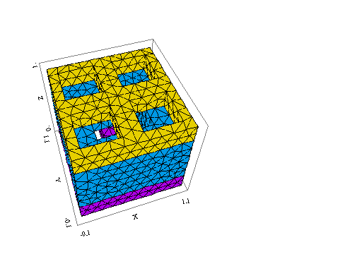
You have misunderstood the way FlexPDE builds 3D figures. Review the documentation sections "User Guide | Using FLexPDE in 3D Problems" and "Technical Notes | Extrusions in 3D". 1. "Regions" are two-dimensional figures laid out in the projection plane. They have no Z coordinates. Removing the Z-coordinates from your region definitions results in Region 4 duplicating (and hiding) region 2. So it is redundant. You still need a fourth region, but is slightly different than the one you have defined. You need: Region 1: the outer material Region 2: the four square holes Region 3: the part of the large square that overlaps the crossbars. Region 4: the part of the large square that overlaps the four square holes. Each of these figures in the projection plane has a different stack of materials (or voids) above it in Z. It is this fact of different material stacks that determines how you need to divide up your regions. 2. You attempted to clarify to FlexPDE the presence of an overhang of the large box into the small boxes by creating duplicate extrusion surfaces, but this is not an effective way to do it. The differing boundaries in each surface mean that the two surface meshes don't coincide and can't be merged. 3. I have modified your script to build what I think you wanted. While it would have been best (clearest) to leave all regions active in all layers and explicitly define the material stacks above each region, I have instead used the implicit FlexPDE rule that regions defined later overlay and hide regions defined earlier. This rule is applied surface-by-surface as the extrusion surfaces are constructed. This choice of mine was made primarily from laziness, because I didn't want to discover and type all the necessary material properties. It makes the attached script a little harder to interpret. I leave it as an exercise to construct the explicit version.
 | |||
Augusto (cdfx) Member Username: cdfx Post Number: 5 Registered: 04-2007 |
Wow bingo! Thanks again Mr Robert! |