| Author | Message | ||
Matthew Hills (mdhills) New member Username: mdhills Post Number: 1 Registered: 01-2007 |
I'm having some difficulty figuring out the correct way of integrating flux. I'm setting up a volume conductor, with some boundaries set up as insulators, and some as electrodes (fixed potentials). What should I do to integrate the flux across one of these electrodes? (sample file attached below) Thanks TITLE 'Disc Cathode' COORDINATES CARTESIAN3 SELECT alias(x) = "X(mm)" alias(y) = "Y(mm)" alias(z) = "Z(mm)" VARIABLES V DEFINITIONS sigma = 0.3 r = 1 EQUATIONS DIV(sigma *GRAD(V)) = 0 EXTRUSION surface 'bottom' z=0 LAYER "medium" surface 'top' z=20 BOUNDARIES REGION 1 'cube' { this is the outer boundary of the system } SURFACE "Bottom" natural(V)=0 {bottom plate is insulating} SURFACE "Top" value(V)=0 {top plate is grounded} START(-20 ,-20 ) value(V)=0 {side walls are grounded} LINE TO (20 ,-20 ) TO (20 ,20 ) TO(-20 ,20 ) to close Region 2 'cathode' {electrode} surface 'bottom' value(V) = -1 start 'cathode_ring' (r,0) arc(center=0,0) to (0,r) to (-r,0) to (0,-r) to close plots contour(V) on x=0 contour(V) on y=0 SUMMARY report( 3.1416 * r * r) as 'Cathode area (mm2)' report(SURF_INTEGRAL(NORMAL(-sigma *GRAD(V) ), 'cube')) as "I(cube)" report(SURF_INTEGRAL(NORMAL(-sigma *GRAD(V) ), "cathode" )) as "I(cathode)" report(SURF_INTEGRAL(NORMAL(-sigma *GRAD(V) ), "bottom","cathode" )) as "I(bottom,cathode)" report(SURF_INTEGRAL(NORMAL(-sigma *GRAD(V) ), "bottom","cathode","medium" )) as "I(bottom,cathode,medium)" report(SURF_INTEGRAL(NORMAL(-sigma *GRAD(V) ), "bottom","cube" )) as "I(bottom,cube)" END | ||
Robert G. Nelson (rgnelson) Moderator Username: rgnelson Post Number: 730 Registered: 06-2003 |
All of your integrals produce numbers. Is there something you don't like about them? | ||
Matthew Hills (mdhills) Junior Member Username: mdhills Post Number: 3 Registered: 01-2007 |
Heh. Yup, all of the integrals produce numbers ;-) In the geometry, I'm trying to establish an insulating plane as the bottom surface, with an electrode at a fixed potential. The sides and top of the volume conductor are grounded. I'd like to calculate how much current is flowing into or out of the conductor through either the small electrode in the bottom plate, or through the grounded sides/top of the conductor. My expectation is that: SURF_INTEGRAL(NORMAL(-sigma *GRAD(V) ), "bottom","cathode" ) will calculate the current in through the small bottom electrode, while SURF_INTEGRAL(NORMAL(-sigma *GRAD(V) ), 'cube') will calculate the current out through the sides/top of the cube. I'd expect these to be equal. I'd also expect the magnitude to be somewhat close to a theoretical value of: 4*r*sigma=1.2 (resistance for a planar disc electrode should be 1/(4*r*sigma)) I must be doing something knuckle-headed. Matt | ||
Matthew Hills (mdhills) Member Username: mdhills Post Number: 4 Registered: 01-2007 |
I think I figured out how I integrate the flow through the sides/top (don't ask me why I didn't try this from the outset): SURF_INTEGRAL(NORMAL(sigma *GRAD(V) ), "cubesides" ) +SURF_INTEGRAL(NORMAL(sigma *GRAD(V) ), "top" )) Still having trouble expressing proper integral for the flow through the bottom surface at the "cathode" region. (I'd expect this flow to be the negative of the integral through the top and sides) Thanks, Matt | ||
Robert G. Nelson (rgnelson) Moderator Username: rgnelson Post Number: 732 Registered: 06-2003 |
Several factors make this problem hard to evaluate: 1) The finite element solution fits polynomial patches to the solution, V, refining the mesh until the estimated uncertainty in V is ERRLIM (default 0.002). Derivatives of the solution are much less accurate, as you can see if you fit a Gaussian, for example, with a network of straight line segments. 2) The switch of boundary conditions from V=-1 to Natural(v)=0 at the boundary of the cathode creates a singularity in dz(V) which is impossible to fit or integrate accurately with a finite element mesh. The attached plot shows a cylindrical 2D model of dz(V) with a very dense mesh. 3) Because of poor mesh resolution of the bottom surface gradient, you must consider the integral on the bottom surface of the cube (nominally zero, but nonzero near the cathode because of interpolation errors) as part of the integral over the cathode. 4) the outer surface of the cube has large area with very small gradient. The value tolerance on V allows rather large percentage fluctuations in V just inside the cube surface, and hence rather large percentage fluctuation in the surface gradients. Although the actual fluctuation is small, multiplying by a very large area can create a significant error in the integral. 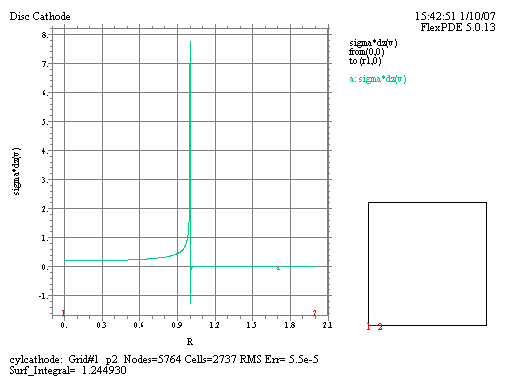 | ||
Matthew Hills (mdhills) Member Username: mdhills Post Number: 5 Registered: 01-2007 |
Hi Robert, I appreciate your feedback on this - with full inclusion of hte bottom plate and tightening the error tolerances, was able to get pretty good agreement. Think it gives me enough to work with my more complex models. Is there a common adjustment to the geometry that would help to soften the numerical difficulties here? Thanks, Matthew | ||
Robert G. Nelson (rgnelson) Moderator Username: rgnelson Post Number: 733 Registered: 06-2003 |
The juxtaposition of dz(V)=0 and dz(V)/=0 is the main problem. This can be eased by making the cathode a shape that allows the derivative to transition smoothly from nonzero to zero. A hemisphere, for example, or anything with a rounded side. In the case of a hemisphere, the radial derivative is constant over the surface, but the z component goes to zero as it meets the bottom insulator. (The planar cathode could be considered a rounded edge with a vanishing radius of curvature. This requires a cell size like a quarter of zero to model it accurately....) The outer surface errors can only be addressed by more mesh density and/or tighter error limits. You could try RESOLVE(dx(V)) RESOLVE(dy(V)) RESOLVE(dz(V)). This puts the derivatives into the error measure. But ultimately, it will just make the mesh more dense. Conceivably, you could put a CONSTRAINT on the total surface integral (=0), but I haven't tried this. |