| Author | Message | ||||
Jerome Jonnet (tintin) Member Username: tintin Post Number: 4 Registered: 02-2004 |
Hello, I'm trying to build a cell in which there is a hole (spherical void). What is the best solution: 2 regions or extrusion ? Anyway, I would need some help on each method ... Thanks for your help ! Jerome | ||||
Robert G. Nelson (rgnelson) Moderator Username: rgnelson Post Number: 459 Registered: 06-2003 |
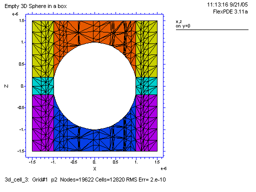
You didn't say whether you want a 2D or a 3D model. For a 2d model, simply select cylindrical coordinates and walk a single boundary containing the outside of the (cylindrical) box, the axis of the cylinder and the spherical surface. See attached "2d_spherebox.pde". For a 3d model in a rectangular box, you need two regions and three layers. Layers 1 and 3 are the contents of the box. Layer 2 contains Limited Region 2, which is the sphere. To make the sphere empty, use "Layer 2 VOID". Otherwise, set its parameters in place of "void". See attached "3d_spherebox.pde".
| ||||
Jerome Jonnet (tintin) Member Username: tintin Post Number: 5 Registered: 02-2004 |
Hi, Thank you for your reply ... You're right, I forgot to say that I wanted a 3D model ... I have tried by myself and found the same result as yours, but there are still problems: 1) my version does not recognise "to close". I have put "to finish" to end the region 1. 2) "limited region 2" does not work as well, I have now "region 2". 3) when I run the file, I have an error "divided by zero on R0 in the definition of zsphere ... If I put "zsphere = if R0^2>(x^2+y^2) then sqrt(R0^2-(x^2+y^2)) else 0", then it runs, but goes wrong, the meshing is taking time and too many cells are created ... I have to stop the run ! I think the point to solve now is the last one ... What do you think of it ? Jerome | ||||
Jerome Jonnet (tintin) Member Username: tintin Post Number: 6 Registered: 02-2004 |
Hi again, The size of the void and the cube is important for the number of cells (I should have found it much earlier ...). If I reduce both size, the mesh building is ok and the file is running correctly ... According to the visualisation of grid, the formulation with "if then else" seems ok. Thank you for your help in the understanding of the problem ... I have now to solve the exact equations with the correct boundary conditions. Jerome
| ||||
Robert G. Nelson (rgnelson) Moderator Username: rgnelson Post Number: 460 Registered: 06-2003 |
I gather you are using FlexPDE version 3, since versions 4 and 5 run the problem correctly as I posted it. Version 3 is not able to handle vertical dividing surfaces, as arise on the waistline of the sphere. You need to introduce a cylindrical waist band to avoid the problem. See the 3d_sphere.pde sample that came with version 3 for an example of how to do this. | ||||
Jerome Jonnet (tintin) Member Username: tintin Post Number: 7 Registered: 02-2004 |
My previous file is working properly if the number of cells is quite large, otherwise my void is not really spherical !!! Now, if I try to build a small waist band to handle the vertical surface, it doesn't work any more and I don't understand why ... Attached is the last version. Thanks !
| ||||
Robert G. Nelson (rgnelson) Moderator Username: rgnelson Post Number: 462 Registered: 06-2003 |
1) You have constructed a goofy equation for the sphere. Look again at the example 3D_sphere.pde. 2) In version 3, the waist band must continue as a layer throughout the outside material. You cannot drop discontinuously to zero. See attached.
 | ||||
Jerome Jonnet (tintin) Member Username: tintin Post Number: 8 Registered: 02-2004 |
Ok, it's perfect ! Thanks again for your support ! Jerome | ||||
Jerome Jonnet (tintin) Member Username: tintin Post Number: 10 Registered: 02-2004 |
Hi ! I want to define boundary conditions on the cube faces which are extruded. I use VALUE to impose the 6 components of stress on these 4 faces. Unfortunately, when I run the file, I first have an "Unknown floating point error", and then the second run works but give weird results ... Is the command right : Region 1 start(-Lx/2-1e-9,-Ly/2-1e-9) line to(Lx/2+1e-9,-Ly/2-1e-9) { y negatif } line to (Lx/2+1e-9,Ly/2+1e-9) { x positif } value(sz) = s33_ypos value(sx) = s11_ypos value(sy) = s22_ypos value(sxy) = s12_ypos value(sxz) = s13_ypos value(syz) = s23_ypos line to (-Lx/2-1e-9,Ly/2-1e-9) { y positif } line to finish { x negatif } Thanks for your help ... | ||||
Robert G. Nelson (rgnelson) Moderator Username: rgnelson Post Number: 495 Registered: 06-2003 |
I need to see the whole script to see how these statements relate to the rest of the problem description. I don't know why you are using stresses as variables. Usually the stresses arise as derivatives of displacements. | ||||
Jerome Jonnet (tintin) Member Username: tintin Post Number: 11 Registered: 02-2004 |
Ok, here is the whole script ... As you can see, I am first using a cubic pore within my cubic domain as I have some difficulties to define a hydrostatic pressure in cartesian coordinates. I use stresses as variables because I know the stresses for the boundary conditions, which ones I want to impose, and not the displacements ... Thus, I solve a bi-potential equation to calculate the whole stress field within the material. Do you think the problem is not right ? Thanks !
| ||||
Robert G. Nelson (rgnelson) Moderator Username: rgnelson Post Number: 496 Registered: 06-2003 |
When I run this problem, it dies trying to compute Cosh(9427). This value is not representable in the computer. It would appear that some of that horrible arithmetic you have there is badly posed. Why not start out with simpler coefficients, until you get a working system? By the way, you can impose stresses on a displacement model using Natural boundary conditions. See the notes to "Samples | Steady_State | Stress | Elasticity.pde". | ||||
Jerome Jonnet (tintin) Member Username: tintin Post Number: 12 Registered: 02-2004 |
You are right, the problem comes from my definitions ... Anyway, I have to use it as a boundary condition, which is calculated from Maple and Matlab ... I will have a detailed look at it ! For the displacement model, I am not so sure that this is the best solution for me. As I said for the boundary conditions, I have to impose a stress field, and not only a surface load vector defined by "load" or "natural", which means I loose some components !!! Do you see what I mean ? I enclose a simplified file with a displacement model, in which I can't reproduce the stress field around the cubic pore. Thanks !
| ||||
Jerome Jonnet (tintin) Member Username: tintin Post Number: 13 Registered: 02-2004 |
I have another question: this is about "RESOLVE". I want to use it on the function I impose as a boundary condition because this function needs particular attention. However, I am not sure to use it correctly. Each time, the process takes too much memory and I have to kill flex ... Is there any simple way to tell directly to Flex where to make a fine mesh ? Thanks ! | ||||
Robert G. Nelson (rgnelson) Moderator Username: rgnelson Post Number: 499 Registered: 06-2003 |
You can specify mesh density explicitly using the MESH_SPACING control. Applied to a region, MESH_SPACING defines the maximum distance between nodes in the volume. Applied to a boundary, MESH_SPACING defines the maximum distance between nodes on the boundary. MESH_SPACING values can be functions of space coordinates. See MESH_SPACING in the Help Index. Other references and example problems are listed in the main article. | ||||
Jerome Jonnet (tintin) Member Username: tintin Post Number: 14 Registered: 02-2004 |
Hi Mr Nelson, I have still problems to adapt my stress model to a displacement model, as explained in a previous posting. Do you think it is possible to impose a complete stress field (I mean, 6 components) and not only surface normal components ? Thank you for your help. Regards,
| ||||
Robert G. Nelson (rgnelson) Moderator Username: rgnelson Post Number: 500 Registered: 06-2003 |
In a "real" 2D object, the only way to impose distortions is through application of body forces and boundary forces. These forces are of necessity two-component forces. The six components of stress arise from a distribution of two-component forces over the body. I infer, therefore, that the six stress components you want to impose are the result of some preliminary calculation that has converted applied force to stress state. Perhaps you could examine the input of that calculation to determine what the applied force was, and use that as boundary conditions to a displacement model in FlexPDE? The fact that the displacement model consists of two second-order equations means that there are only four integration constants to be determined by boundary conditions, one per dimension per face. | ||||
Jerome Jonnet (tintin) Member Username: tintin Post Number: 15 Registered: 02-2004 |
You are right, the stress components I want to impose are the result of preliminary calculations ... But this a conversion from a 3D Airy stress function to the stress components, and not from an applied force. So I really need to impose this stress field on boundaries ... Anyway, is the stress model wrong ? I mean, I only solve the Beltrami' equations, which directly give the stress field in the body ... It should be correct ??? Is there any difference with a possible displacement model (accuracy, memory, computation time) ? Thanks again for your time and help ! |