| Author | Message | |||
RyanL (min) New member Username: min Post Number: 1 Registered: 06-2009 |
Hi everyone: I am having trouble modeling my model. I have included my script. What I want to do is to change the limited region 4 into multiple cylindrical rods. I tried to define one more layer in the extrusion with the +/- sqrt(max(r^2-y^2,0)) function. However, that only gives me one cylindrical rod. I am wondering if there is anyway to make it so that every rectangular prism in my region 4 become a cylindrical rod. Thank you
| |||
Robert G. Nelson (rgnelson) Moderator Username: rgnelson Post Number: 1270 Registered: 06-2003 |
Two surfaces defined as z=+-sqrt(R^2-(x-x0)^2), with x0 the x-coordinate of the axis, will give you a single cylinder. To define a surface containing a large number of these, you will have to do one of the following: 1) explicitly combine all the rods in the definition of the surfaces, as for example Z=zreference + sum(i,1,nrods,zform(xreference+(i-1)*xspace)), where you have defined zform(xf)=sqrt(max(0,R^2-(x-xf)^2)) 2) Put the region definition inside a repeat, defining the z coordinate of the surface in each region as one of the components of the sum above. Incidentally, in your script, regions 2, 3 and 5 all have the same projection, so they should properly be combined into a single region. See "Help->Tech Notes->Extrusions in 3D". | |||
RyanL (min) New member Username: min Post Number: 2 Registered: 06-2009 |
Hi: I am not sure that if I quite understand. Is it possible for you to post a working example so I can play around with? Thank you so much in advance. Also I tried to put my region 2,3 and 5 together; however, it gives me error saying that no common cell. I am not sure where I did wrong. The attached file is the merged region 2,3 and 5 Thank you so much
| |||
Marek Nelson (mgnelson) Moderator Username: mgnelson Post Number: 124 Registered: 07-2007 |
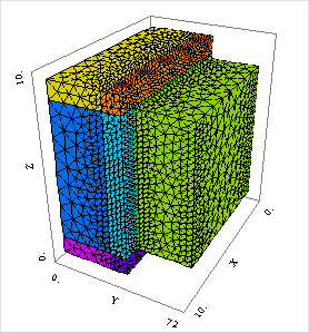
This error appears to be due to the very thin "Al2O3 Block" layer. Thin layers can cause difficulty in gridding. The best thing to do in these cases is to add manual grid density statements (MESH_SPACING or MESH_DENSITY), or to use scaled coordinates (see "Coordinate Scaling" in the Help index.) I am not sure why you got the error in one script but not the other. They should have acted the same. Looking at your domain, I think this would be much easier to fit into the extrusion model of FlexPDE if you were to turn your device on the side. Then the round rods that you want will be simply circles in the domain definition, rather than try to define the surfaces of the rods. I have attached an example script where I have done this. There are no equations or BCs and the dimensions are just arbitrary, so you will have to make some changes to fit your system.
 | |||
RyanL (min) Junior Member Username: min Post Number: 3 Registered: 06-2009 |
Hi: I have thought about turning the device on the side; however, I would be missing a boundary condition definition on one of the vertical surface. I think this is due to the fact that the BC of the 4 surrounding sides are defined all at once. I am wondering if there is a way to define different BC of the surrounding side of a single block. Thank you | |||
Marek Nelson (mgnelson) Moderator Username: mgnelson Post Number: 125 Registered: 07-2007 |
You can have different BCs for each segment of a bounding path and on each region of each extrusion surface. This allows you to have different BCs, for example, on all sides of a cube: Region 1 surface 1 value(u)=1 surface 2 value(u)=2 start (0,0) value(u)=3 line to (1,0) value(u)=4 line to (1,1) value(u)=5 line to (0,1) value(u)=6 line to close See "Boundary Conditions, 3D" in the Help index. |